MUF-P7C Ardupliot Firmware
Where to Buy: MUF-P7C.
Overview
load firmware
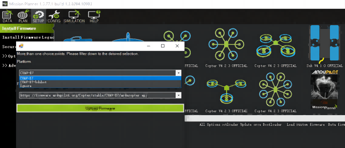
Online burning firmware:
- Connect the flight controller to the computer,
- open the ground station
- Click the "SETUP" "install firmware" >select the Platform (CUAV X7)
- Wait for the burning to complete.
Load local firmware
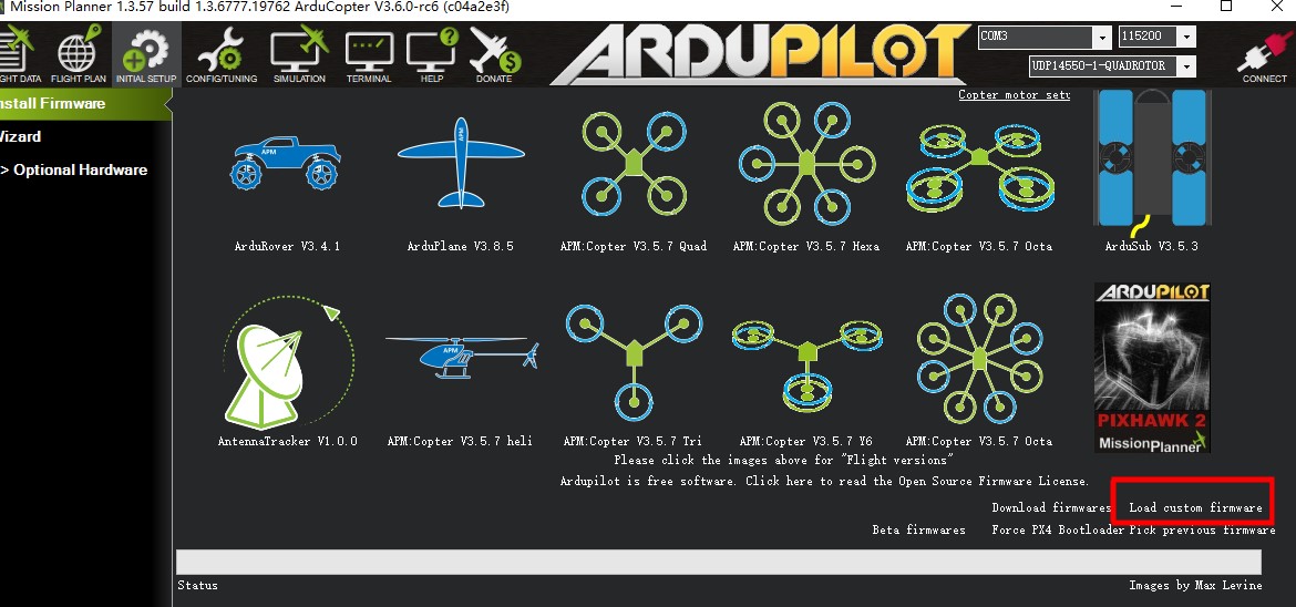
- Please download the firmware to the local first:
- Copter
- HeilCopter
- Plane(and VTOL)
- Rower
- Sub/Boat
- Select to load custom firmware
- select local firmware file
UART MAP
- SERIAL0 = console = USB
- SERIAL1 = Telemetry1 = USART2
- SERIAL2 = Telemetry2 = USART6
- SERIAL3 = GPS1 = USART1
- SERIAL4 = USER = UART4
- SERIAL5 = USER = UART8
- SERIAL6 = USER = UART7
- SERIAL7 = USER = OTG
RC input
The RCIN interface supports all protocols (SBUS/PPM/DSM) except CRSF; for CRSF and receivers with bidirectional protocols with telemetry, it needs to be connected to a UART interface, such as Serial6 (UART4). Here is the setup tutorial:
- SERIAL6_PROTOCOL set to 23;
- FPort:SERIAL6_OPTIONS set to 15;
- CRSF:SERIAL6_OPTIONS set to 0;
- SRXL2:SERIAL6_OPTIONS set to 4,And only connect the TX pin.
Battery Monitoring
MUF-P7C comes standard with CAN PMU lite ammeter (Dronecan),CAN PMU lite connect to Power C.
You need to set the following parameters:
- BATT_MPNITOR=8
- CAN_P1_DRIVER=1
- CAN_P2_DRIVER=1
If you are using an analog battery monitor(such as HV_PM power module),connect to the Power A connector and set the following parameters:
- BATT_MONITOR=4
- BATT_VOLT_MULT=18
- BATT_V0LT_PIN=16
- BATT_CURR_PIN=17
- BATT_AMP_PERVLT=24
Compass
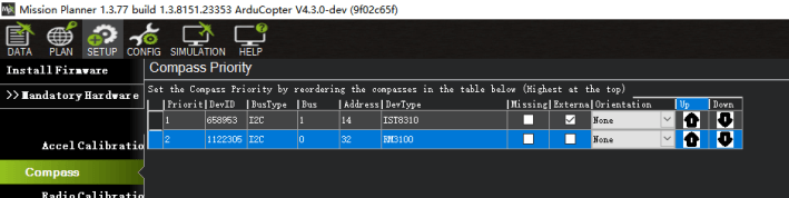
Inside the ® is an RM3100 magnetic compass. Generally, the flight control is located inside the drone, and the magnetic field environment is more complicated. It is reasonable to use an external compass (such as one on a GPS) as the primary compass; always ensure that the external compass is placed in preference to the internal compass.
If your compass is set up like this:
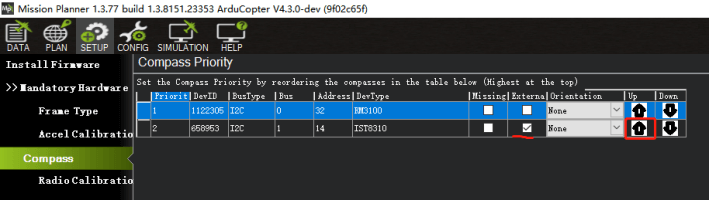
Please set the external compass as the first compass according to the following figure.
PWM Output
The MUF-P7C supports up to 14 PWM outputs. All 14 outputs support all normal PWM output formats. All outputs, except 13 and 14, also support DShot.
The 14 FMU PWM outputs are divided into 4 groups:
- M1~M4 in group1
- M5~M8 in group2
- M9~M12 in group3
- M13、M14 in group4
GPIOs
M1~M14 can be used as GPIO (relay, button, RPM, camera shutter trigger (level), etc.). To use them, you need to set the output SERVOx_FUNCTION to -1 (GPIO).
The numbering of the GPIOs for PIN variables in ArduPilot is:
- PWM1(M1) 50
- PWM2(M2) 51
- PWM3(M3) 52
- PWM4(M4) 53
- PWM5(M5) 54
- PWM6(M6) 55
- PWM7(M7) 56
- PWM8(M8) 57
- PWM9(M9) 58
- PWM10(M10) 59
- PWM11(M11) 60
- PWM12(M12) 61
- PWM13(M13) 62
- PWM14(M14) 63 Take X7+ M14 as the relay as an example, set Relay_PIN=63.
Analog inputs
CUAV X7 Series has 3 analog inputs (ADC6.6v, ADC3.3v, Rssi)
- ADC Pin18 -> ADC 6.6V
- ADC Pin4 -> ADC 3.3V
- RSSI PIN=6